
|
www.riscos.com Technical Support: |
This appendix defines three file formats used by the Desktop tools to store processed code and the format of debugging data used by DDT:
Desktop tools language processors such as CC and ObjAsm generate processed code output as AOF files. An ALF file is a collection of AOF files constructed from a set of AOF files by the LibFile tool. The Link tool accepts a set of AOF and ALF files as input, and by default produces an executable program file as output in AIF.
Throughout this appendix the terms byte, half word, word, and string are used to mean the following:
Byte: 8 bits, considered unsigned unless otherwise stated, usually used to store flag bits or characters.
Half word:16 bits, or 2 bytes, usually unsigned. The least significant byte has the lowest address (DEC/Intel byte sex, sometimes called little endian). The address of a half word (i.e. of its least significant byte) must be divisible by 2.
Word: 32 bits, or 4 bytes, usually used to store a non-negative value. The least significant byte has the lowest address (DEC/Intel byte sex, sometimes called little endian). The address of a word (i.e. of its least significant byte) must be divisible by 4.
String: A sequence of bytes terminated by a NUL (0X00) byte. The NUL is part of the string but is not counted in the string's length. Strings may be aligned on any byte boundary.
Note: a word consists of 32 bits, 4-byte aligned; within a word, the least significant byte has the lowest address. This is DEC/Intel, or little endian, byte sex, not IBM/Motorola byte sex.
There are two sorts of AOF or ALF: little-endian and big-endian.
In little-endian AOF or ALF, the least significant byte of a word or half-word has the lowest address of any byte in the (half-)word. This byte sex is used by DEC, Intel and Acorn, amongst others.
In big-endian AOF or ALF, the most significant byte of a (half-)word has the lowest address. This byte sex is used by IBM, Motorola and Apple, amongst others.
For data in a file, address means 'offset from the start of the file'.
There is no guarantee that the endian-ness of an AOF or ALF file will be the same as the endian-ness of the system used to process it (the endian-ness of the file is always the same as the endian-ness of the target ARM system).
The two sorts of AOF or ALF cannot, be mixed (the target system cannot have mixed endian-ness: it must have one or the other). Thus the ARM linker will accept inputs of either sex and produce an output of the same sex, but will reject inputs of mixed endian-ness.
Strings and bytes may be aligned on any byte boundary.
AOF and ALF fields defined in this appendix make no use of half-words and align words on 4-byte boundaries.
Within the contents of an AOF or ALF file the alignment of words and half-words is defined by the use to which AOF or ALF is being put.
For all current ARM-based systems, words are aligned on 4-byte boundaries and half-words on 2-byte boundaries.
Fields not explicitly defined by this appendix are implicitly reserved to Acorn. It is required that all such fields be zeroed. Acorn may ascribe meaning to such fields at any time, but will usually do so in a manner which gives no new meaning to zeroes.
A chunk is accessed via a header at the start of the file. The header contains the number, size, location and identity of each chunk in the file. The size of the header may vary between different chunk files but is fixed for each file. Not all entries in a header need be used, thus limited expansion of the number of chunks is permitted without a wholesale copy. A chunk file can be copied without knowledge of the contents of the individual chunks.
Graphically, the layout of a chunk file is as follows:
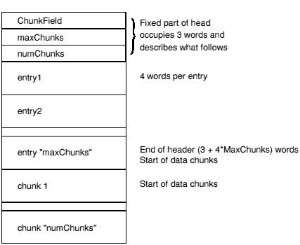
ChunkFileId marks the file as a chunk file. Its value is 0xC3CBC6C5. The endian-ness of the chunk file can be deduced from this value (if, when read as a word, it appears to be 0xC5C6CBC3 then each word value must be byte-reversed before use).
The MaxChunks field defines the number of the entries in the header, fixed when the file is created. The NumChunks field defines how many chunks are currently used in the file, which can vary from 0 to MaxChunks. The value of NumChunks is redundant as it can be found by scanning the entries.
Each entry in the header comprises four words in the following order:
The chunkId field provides a conventional way of identifying what type of data a chunk contains. It is split into two parts. The first four characters contain a unique name allocated by a central authority (Acorn). The remaining four characters can be used to identify component chunks within this domain. The 8 characters are stored in ascending address order, as if they formed part of a NUL-terminated string (which they do not), independently of endian-ness.
For AOF files, the first part of each chunk's name is OBJ_; the second components are defined later in this section.
Each piece of an object file is stored in a separate, identifiable, chunk. AOF defines five chunks as follows:
| Chunk | Chunk Name |
|---|---|
| Header | OBJ_HEAD |
| Areas | OBJ_AREA |
| Identification | OBJ_IDFN |
| Symbol Table | OBJ_SYMT |
| String Table | OBJ_STRT |
Only the header and areas chunks must be present, but a typical object file will contain all five of the above chunks.
Each name in an object file is encoded as an offset into the string table, stored in the OBJ_STRT chunk (see String table chunk (OBJ_STRT)). This allows the variable-length nature of names to be factored out from primary data formats.
A feature of chunk file format is that chunks may appear in any order in the file. However, language processors which must also generate other object formats - such as Unix's a.out format - should use this flexibility cautiously.
A language translator or other system utility may add additional chunks to an object file, for example a language-specific symbol table or language-specific debugging data, so it is conventional to allow space in the chunk header for additional chunks; space for eight chunks is conventional when the AOF file is produced by a language processor which generates all five chunks described here.
The header chunk should not be confused with the chunk file's header.
The AOF header is logically in two parts, though these appear contiguously in the header chunk. The first part is of fixed size and describes the contents and nature of the object file. The second part is variable in length (specified in the fixed part) and is a sequence of area declarations defining the code and data areas within the OBJ_AREA chunk.
The AOF header chunk (OBJ_HEAD) has the following format:
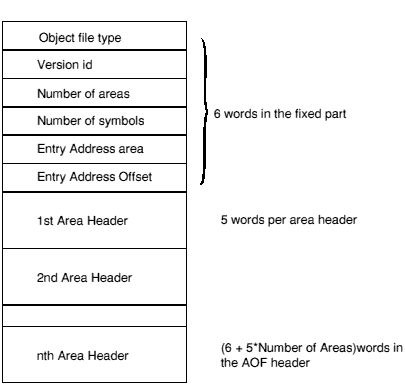
0xC5E2D080 marks the file as being in relocatable object format (the usual output of compilers and assemblers and the usual input to the linker).
The endian-ness of the object code can be deduced from this value and shall be identical to the endian-ness of the containing chunk file.
Encodes the version of AOF to which the object file complies: version 1.50 is denoted by decimal 150; version 2.00 by 200; version 3.10 by 310; and this version 3.11 by decimal 311 (0x137).
The code and data of the object file is presented as a number of separate areas, in the OBJ_AREA chunk, each with a name and some attributes (see below). Each area is declared in the (variable-length) part of the header which immediately follows the fixed part. The value of the Number of Areas field defines the number of areas in the file and consequently the number of area declarations which follow the fixed part of the header.
If the object file contains a symbol table chunk OBJ_SYMT, then this field defines the number of symbols in the symbol table.
One of the areas in an object file may be designated as containing the start address of any program which is linked to include the file. If this is the case, the entry address is specified as an Entry Area Index, Entry Offset pair. Entry Area Index, in the range 1 to Number of Areas, gives the 1-origin index in the following array of area headers of the area containing the entry point. The entry address is defined to be the base address of this area plus Entry Offset.
A value of 0 for area-index signifies that no program entry address is defined by this AOF file.
The area headers follow the fixed part of the AOF header. Each area header has the following form:
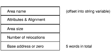
Each area within an object file must be given a name which is unique amongst all the areas in the file. Area Name gives the offset of that name in the string table (stored in the OBJ_STRT chunk - see String table chunk (OBJ_STRT)).
This field gives the size of the area in bytes, which must be a multiple of 4. Unless the Uninitialised bit (bit 4) is set in the area attributes (see Attributes and Alignment), there must be this number of bytes for this area in the OBJ_AREA chunk. If the Uninitialised bit is set, then there shall be no initialising bytes for this area in the OBJ_AREA chunk.
This word specifies the number of relocation directives which apply to this area, (equivalently: the number of relocation records following the area's contents in the OBJ_AREA chunk - see Format of the areas chunk).
Each area has a set of attributes encoded in the most-significant 24 bits of the Attributes + Alignment word. The least-significant 8 bits of this word encode the alignment of the start of the area as a power of 2 and shall have a value between 2 and 32 (this value denotes that the area should start at an address divisible by 2alignment).
The linker orders areas in a generated image first by attributes, then by the (case-significant) lexicographic order of area names, then by position of the containing object module in the link list. The position in the link list of an object module loaded from a library is not predictable.
The precise significance to the linker of area attributes depends on the output being generated.
Bit 8 encodes the absolute attribute and denotes that the area must be placed at its Base Address. This bit is not usually set by language processors.
Bit 9 encodes the code attribute: if set the area contains code; otherwise it contains data.
Bits 10, 11 encode the common block definition and common block reference attributes, respectively.
Bit 10 specifies that the area is a common block definition.
Bit 11 defines the area to be a reference to a common block, and precludes the area having initialising data (see Bit 12, below). In effect, bit 11 implies bit 12.
If both bits 10 and 11 are set, bit 11 is ignored.
Common areas with the same name are overlaid on each other by the linker. The Area Size field of a common definition area defines the size of a common block. All other references to this common block must specify a size which is smaller or equal to the definition size. If, in a link step, there is more than one definition of an area with the common definition attribute (area of the given name with bit 10 set), then each of these areas must have exactly the same contents. If there is no definition of a common area, its size will be the size of the largest common reference to it.
Although common areas conventionally hold data, it is quite legal to use bit 10 in conjunction with bit 9 to define a common block containing code. This is most useful for defining a code area which must be generated in several compilation units but which should be included in the final image only once.
Bit 12 encodes the zero-initialised attribute, specifying that the area has no initialising data in this object file, and that the area contents are missing from the OBJ_AREA chunk. Typically, this attribute is given to large uninitialised data areas. When an uninitialised area is included in an image, the linker either includes a read-write area of binary zeroes of appropriate size, or maps a read-write area of appropriate size that will be zeroed at image start-up time. This attribute is incompatible with the read-only attribute (see Bit 13, below).
Whether or not a zero-initialised area is re-zeroed if the image is re-entered is a property of the relevant image format and/or the system on which it will be executed. The definition of AOF neither requires nor precludes re-zeroing.
To summarise, bits 10, 11 and 12 interact as follows:
| 12 | 11 | 10 | Interaction | |
|---|---|---|---|---|
| 0 | 0 | 1 | Initialised common definition | |
| 0 | 1 | 1 | Initialised common definition | |
| 0 | 1 | 0 | Uninitialised reference to common block | |
| 1 | 0 | 1 | Uninitialised reference to common block | |
| 1 | 1 | 0 | Uninitialised reference to common block | |
| 1 | 1 | 1 | Uninitialised reference to common block | |
| 1 | 0 | 0 | Zero-initialised (bss = unnamed common reference) |
So, an initialised common definition is inferred if bit 10 is set and bit 11 is not, a Zero-initialised area is inferred if bit 12 is set and both bits 10 and 11 are unset, all other bit combinations infer an uninitialised reference to common block.
Bit 13 encodes the read only attribute and denotes that the area will not be modified following relocation by the linker. The linker groups read-only areas together so that they may be write protected at run-time, hardware permitting. Code areas and debugging tables should have this bit set. The setting of this bit is incompatible with the setting of bit 12.
Bit 14 encodes the position independent (PI) attribute, usually only of significance for code areas. Any reference to a memory address from a PI area must be in the form of a link-time-fixed offset from a base register (e.g. a PC-relative branch offset).
Bit 15 encodes the debugging table attribute and denotes that the area contains symbolic debugging tables. The linker groups these areas together so they can be accessed as a single continuous chunk at or before run-time (usually, a debugger will extract its debugging tables from the image file prior to starting the debuggee).
Usually, debugging tables are read-only and, therefore, have bit 13 set also. In debugging table areas, bit 9 (the code attribute) is ignored.
Bits 16-19 encode additional attributes of code areas and shall be non-0 only if the area has the code attribute (bit 9 set).
Bit 16 encodes the 32-bit PC attribute, and denotes that code in this area complies with a 32-bit variant of the ARM Procedure Call Standard (APCS). For details, refer to '32-bit PC vs 26-bit PC'. Such code may be incompatible with code which complies with a 26-bit variant of the APCS.
Bit 17 encodes the reentrant attribute, and denotes that code in this area complies with a reentrant variant of the ARM Procedure Call Standard.
Bit 18, when set, denotes that code in this area uses the ARM's extended floating-point instruction set. Specifically, function entry and exit use the LFM and SFM floating-point save and restore instructions rather than multiple LDFEs and STFEs. Code with this attribute may not execute on older ARM-based systems.
Bit 19 encodes the No Software Stack Check attribute, denoting that code in this area complies with a variant of the ARM Procedure Call Standard without software stack-limit checking. Such code may be incompatible with code which complies with a limit-checked variant of the APCS.
Bits 20-27 encode additional attributes of data areas, and shall be non-0 only if the area does not have the code attribute (bit 9) unset.
Bit 20 encodes the based attribute, denoting that the area is addressed via link-time-fixed offsets from a base register (encoded in bits 24-27). Based areas have a special role in the construction of shared libraries and ROM-able code, and are treated specially by the linker.
Bit 21 encodes the Shared Library Stub Data attribute. In a link step involving layered shared libraries, there may be several copies of the stub data for any library not at the top level. In other respects, areas with this attribute are treated like data areas with the common definition (bit 10) attribute. Areas which also have the zero initialised attribute (bit 12) are treated much the same as areas with the common reference (bit 11) attribute.
This attribute is not usually set by language processors, but is set only by the linker.
Bits 22-23 are reserved and shall be set to 0.
Bits 24-27 encode the base register used to address a based area. If the area does not have the based attribute then these bits shall be set to 0.
Bits 28-31 are reserved and shall be set to 0.
| Bit | Mask | Attribute Description |
|---|---|---|
| 8 | 0x00000100 | Absolute attribute |
| 9 | 0x00000200 | Code attribute |
| 10 | 0x00000400 | Common block definition |
| 11 | 0x00000800 | Common block reference |
| 12 | 0x00001000 | Uninitialised (0-initialised) |
| 13 | 0x00002000 | Read only |
| 14 | 0x00004000 | Position independent |
| 15 | 0x00008000 | Debugging tables |
| Code areas only | ||
| 16 | 0x00010000 | Complies with the 32-bit APCS |
| 17 | 0x00020000 | Reentrant code |
| 18 | 0x00040000 | Uses extended FP inst set |
| 19 | 0x00080000 | No software stack checking |
| Data areas only | ||
| 20 | 0x00100000 | Based area |
| 21 | 0x00200000 | Shared library stub data |
| 24-27 | 0x0F000000 | Base register for based area |
The areas chunk (ChunkId of OBJ_AREA) contains the actual areas (code, data, zero- initialised data, debugging data, etc.) plus any associated relocation information. Graphically, an area's layout is:
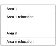
An area is simply a sequence of byte values. The endian-ness of the words and half-words within it shall agree with that of the containing AOF file.
An area is followed by its associated table of relocation directives (if any). An area is either completely initialised by the values from the file or is initialised to zero, as specified by bit 12 of its area attributes.
Both the area contents and the table of relocation directives are aligned to 4-byte boundaries.
A relocation directive describes a value which is computed at link time or load time, but which cannot be fixed when the object module is created.
In the absence of applicable relocation directives, the value of a byte, halfword, word or instruction from the preceding area is exactly the value that will appear in the final image.
A field may be subject to more than one relocation.
Pictorially, a relocation directive looks like:
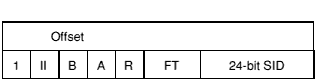
Offset is the byte offset in the preceding area of the subject field to be relocated by a value calculated as described below.
The interpretation of the 24-bit SID field depends on the A bit.
If A (bit 27) is 1, the subject field is relocated (as further described below) by the value of the symbol of which SID is the 0-origin index in the symbol table chunk.
If A (bit 27) is 0, the subject field is relocated (as further described below) by the base of the area of which SID is the 0-origin index in the array of areas, (or, equivalently, in the array of area headers).
The 2-bit field type FT (bits 25, 24) describes the subject field:
| 00 | the field to be relocated is a byte |
| 01 | the field to be relocated is a half-word (2 bytes) |
| 10 | the field to be relocated is a word (4 bytes) |
| 11 | the field to be relocated is an instruction or instruction sequence |
Bytes, halfwords and instructions may only be relocated by values of suitably small size. Overflow is faulted by the linker.
An ARM branch, or branch-with-link instruction is always a suitable subject for a relocation directive of field type instruction.
If the subject field is an instruction sequence (FT = 11), then Offset addresses the first instruction of the sequence and the II field (bits 29 and 30) constrains how many instructions may be modified by this directive:
| 00 | no constraint (the linker may modify as many contiguous instructions as it needs to) |
| 01 | the linker will modify at most 1 instruction |
| 10 | the linker will modify at most 2 instructions |
| 11 | the linker will modify at most 3 instructions |
The way the relocation value is used to modify the subject field is determined by the R (PC-relative) bit, modified by the B (based) bit.
R (bit 26) = 1 and B (bit 28) = 0 specifies PC-relative relocation: to the subject field is added the difference between the relocation value and the base of the area containing the subject field. In pseudo C:
subject_field = subject_field + (relocation_value - base_of_area_containing(subject_field))
As a special case, if A is 0, and the relocation value is specified as the base of the area containing the subject field, then it is not added and:
subject_field = subject_field - base_of_area_containing(subject_field)
This caters for relocatable PC-relative branches to fixed target addresses.
If R is 1, B is usually 0. If B is 1 this is used to denote that the inter-link-unit value of a branch destination is to be used, rather than the more usual intra-link-unit value (this allows compilers to perform the tail-call optimisation on reentrant code).
R (bit 26) = 0 and B (bit 28) = 0, specifies plain additive relocation: the relocation value is added to the subject field. In pseudo C:
subject_field = subject_field + relocation_value
R (bit 26) = 0 and B (bit 28) = 1, specifies based area relocation. The relocation value must be an address within a based data area. The subject field is incremented by the difference between this value and the base address of the consolidated based area group (the linker consolidates all areas based on the same base register into a single, contiguous region of the output image). In pseudo C:
subject_field = subject_field + (relocation_value - base_of_area_group_containing(relocation_value))
For example, when generating reentrant code, the C compiler will place address constants in an adcon area based on register sb, and load them using sb relative LDRs. At link time, separate adcon areas will be merged and sb will no longer point where presumed at compile time. B type relocation of the LDR instructions corrects for this.
Bit 31 of the relocation flags word shall be 1, and (unless FT bits are 11) bits 29 and 30 shall be 0.
The Number of Symbols field in the fixed part of the AOF header (OBJ_STRT) defines how many entries there are in the symbol table. Each symbol table entry has the following format:
This value is an index into the string table (in chunk OBJ_STRT) and thus locates the character string representing the symbol.
This is only meaningful if the symbol is a defining occurrence (bit 0 of Attributes set), or a common symbol (bit 6 of Attributes set):
is meaningful only if the symbol is a non-absolute defining occurrence (bit 0 of Attributes set, bit 2 unset). In this case it gives the index into the string table for the name of the area in which the symbol is defined (which must be an area in this object file).
The Symbol Attributes word is interpreted as follows:
Specifically:
| 01 | (bit 1 unset, bit 0 set) denotes that the symbol is defined in this object file and has scope limited to this object file (when resolving symbol references, the linker will only match this symbol to references from within the same object file). |
| 10 | (bit 1 set, bit 0 unset) denotes that the symbol is a reference to a symbol defined in another object file. If no defining instance of the symbol is found the linker attempts to match the name of the symbol to the names of common blocks. If a match is found it is as if there were defined an identically-named symbol of global scope, having as its value the base address of the common area. |
| 11 | denotes that the symbol is defined in this object file with global scope (when attempting to resolve unresolved references, the linker will match this definition to a reference from another object file). |
| 00 | Reserved by Acorn. |
Bit 2 encodes the absolute attribute which is meaningful only if the symbol is a defining occurrence (bit 0 set). If set, it denotes that the symbol has an absolute value, for example, a constant. If unset, the symbol's value is relative to the base address of the area defined by the Area Name field of the symbol.
Bit 3 encodes the case insensitive reference attribute which is meaningful only if bit 0 is unset (that is, if the symbol is an external reference). If set, the linker will ignore the case of the symbol names it tries to match when attempting to resolve this reference.
Bit 4 encodes the weak attribute which is meaningful only if the symbol is an external reference, (bits 1,0 = 10). It denotes that it is acceptable for the reference to remain unsatisfied and for any fields relocated via it to remain unrelocated. The linker ignores weak references when deciding which members to load from an object library.
Bit 5 encodes the strong attribute which is meaningful only if the symbol is an external defining occurrence (if bits 1,0 = 11). In turn, this attribute only has meaning if there is a non-strong, external definition of the same symbol in another object file. In this case, references to the symbol from outside of the file containing the strong definition, resolve to the strong definition, while those within the file containing the strong definition resolve to the non-strong definition.
This attribute allows a kind of link-time indirection to be enforced. Usually, a strong definition will be absolute, and will be used to implement an operating system's entry vector having the forever binary property.
Bit 6 encodes the common attribute, which is meaningful only if the symbol is an external reference (bits 1,0 = 10). If set, the symbol is a reference to a common area with the symbol's name. The length of the common area is given by the symbol's Value field (see above). The linker treats common symbols much as it treats areas having the Common Reference attribute - all symbols with the same name are assigned the same base address, and the length allocated is the maximum of all specified lengths.
If the name of a common symbol matches the name of a common area, then these are merged and the symbol identifies the base of the area.
All common symbols for which there is no matching common area (reference or definition) are collected into an anonymous, linker-created, pseudo-area.
Bit 7 is reserved and shall be set to 0.
Bit 8 encodes the code datum attribute which is meaningful only if this symbol defines a location within an area having the Code attribute. It denotes that the symbol identifies a (usually read-only) datum, rather than an executable instruction.
Bit 9 encodes the floating-point arguments in floating-point registers attribute. This is meaningful only if the symbol identifies a function entry point. A symbolic reference with this attribute cannot be matched by the linker to a symbol definition which lacks the attribute.
Bit 10 is reserved and shall be set to 0.
Bit 11 is the simple leaf function attribute which is meaningful only if this symbol defines the entry point of a sufficiently simple leaf function (a leaf function is one which calls no other function). For a reentrant leaf function it denotes that the function's inter-link-unit entry point is the same as its intra-link-unit entry point.
Bits 12-31 are reserved and shall be set to 0.
| Bit | Mask | Attribute Description |
|---|---|---|
| 0 | 0x00000001 | Symbol is defined in this file |
| 1 | 0x00000002 | Symbol has global scope |
| 2 | 0x00000004 | Absolute attribute |
| 3 | 0x00000008 | Case-insensitive attribute |
| 4 | 0x00000010 | Weak attribute |
| 5 | 0x00000020 | Strong attribute |
| 6 | 0x00000040 | Common attribute |
|
Code symbols only | ||
| 8 | 0x00000100 | Code area datum attribute |
| 9 | 0x00000200 | FP args in FP regs attribute |
| 11 | 0x00000800 | Simple leaf function attribute |
The string table chunk contains all the print names referred to from the header and symbol table chunks. This separation is made to factor out the variable length characteristic of print names from the key data structures.
A print name is stored in the string table as a sequence of non-control characters (codes 32-126 and 160-255) terminated by a NUL (0) byte, and is identified by an offset from the start of the table. The first 4 bytes of the string table contain its length (including the length of its length word), so no valid offset into the table is less than 4, and no table has length less than 4.
The endian-ness of the length word shall be identical to the endian-ness of the AOF and chunk files containing it.
This chunk should contain a string of printable characters (codes 10-13 and 32-126) terminated by a NUL (0) byte, which gives information about the name and version of the tool which generated the object file. Use of codes in the range 128-255 is discouraged, as the interpretation of these values is host dependent.
For library files, the first part of each chunk's name is 'LIB_'; for object libraries, the names of the additional two chunks begin with 'OFL_'.
Each piece of a library file is stored in a separate, identifiable chunk, named as follows:
| Chunk | Chunk Name | |
|---|---|---|
| Directory | LIB_DIRY | |
| Time-stamp | LIB_TIME | |
| Version | LIB_VSRN | |
| Data | LIB_DATA | |
| Symbol table | OFL_SYMT | - object code libraries only |
| Time-stamp | OFL_TIME | - object code libraries only |
There may be many LIB_DATA chunks in a library, one for each library member. In all chunks, word values are stored with the same byte order as the target system; strings are stored in ascending address order, which is independent of target byte order.
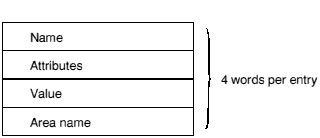
The LIB_DIRY chunk contains a directory of the modules in the library, each of which is stored in a LIB_DATA chunk. The directory size is fixed when the library is created. The directory consists of a sequence of variable length entries, each an integral number of words long. The number of directory entries is determined by the size of the LIB_DIRY chunk.
This is shown pictorially in the following diagram:
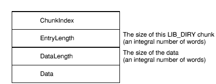
ChunkIndex is a word containing the 0-origin index within the chunk file header of the corresponding LIB_DATA chunk. Conventionally, the first 3 chunks of an OFL file are LIB_DIRY, LIB_TIME and LIB_VSRN, so ChunkIndex is at least 3. A ChunkIndex of 0 means the directory entry is unused.
The corresponding LIB_DATA chunk entry gives the offset and size of the library module in the library file.
EntryLength is a word containing the number of bytes in this LIB_DIRY entry, always a multiple of 4.
DataLength is a word containing the number of bytes used in the data section of this LIB_DIRY entry, also a multiple of 4.
The Data section consists of, in order:
Strings should contain only ISO-8859 non-control characters (codes [0-31], 127 and 128+[0-31] are excluded).
The string field is the name used to identify this library module. Typically it is the name of the file from which the library member was created.
The format of the time stamp is described in Time Stamps. Its value is an encoded version of the last-modified time of the file from which the library member was created.
To ensure maximum robustness with respect to earlier, now obsolete, versions of the ARM object library format:
Applications which write LIB_DIRY or OFL_SYMT entries should ensure that padding is done with NUL (0) bytes; applications which read LIB_DIRY or OFL_SYMT entries should make no assumptions about the values of padding bytes beyond the first, string-terminating NUL byte.
A library time stamp is a pair of words encoding the following:
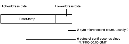
The first word stores the most significant 4 bytes of the 6-byte count; the least significant 2 bytes of the count are in the most significant half of the second word.
The least significant half of the second word contains the microsecond count and is usually 0.
Time stamp words are stored in target system byte order: they must have the same endian-ness as the containing chunk file.
The LIB_TIME chunk contains a 2-word time stamp recording when the library was last modified. It is, hence, 8 bytes long.
The version chunk contains a single word whose value is 1.
A LIB_DATA chunk contains one of the library members indexed by the LIB_DIRY chunk. The endian-ness or byte order of this data is, by assumption, the same as the byte order of the containing library/chunk file.
No other interpretation is placed on the contents of a member by the library management tools. A member could itself be a file in chunk file format or even another library.
An object code library is a library file whose members are files in ARM Object Format (see AOF for details).
An object code library contains two additional chunks: an external symbol table chunk named OFL_SYMT; and a time stamp chunk named OFL_TIME.
The external symbol table contains an entry for each external symbol defined by members of the library, together with the index of the chunk containing the member defining that symbol.
The OFL_SYMT chunk has exactly the same format as the LIB_DIRY chunk except that the Data section of each entry contains only a string, the name of an external symbol, and between 1 and 4 bytes of NUL padding, as follows:
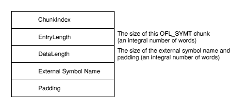
OFL_SYMT entries do not contain time stamps.
The OFL_TIME chunk records when the OFL_SYMT chunk was last modified and has the same format as the LIB_TIME chunk (see Time Stamps).
ARM Image Format (AIF) is a simple format for ARM executable images, which consists of a 128 byte header followed by the image's code, followed by the image's initialised static data.
Two variants of AIF exist:
The two flavours of AIF are distinguished as follows:
The base address of an executable AIF image is the address at which its header should be loaded; its code starts at base + 0x80. The base address of a non-executable AIF image is the address at which its code should be loaded.
The following remarks about executable AIF apply also to non-executable AIF, except that loader code must interpret the AIF header and perform any required decompression, relocation, and creation of zero-initialised data. Compression and relocation are, of course, optional: AIF is often used to describe very simple absolute images.
It is assumed that on entry to a program in ARM Image Format (AIF), the general registers contain nothing of value to the program (the program is expected to communicate with its operating environment using SWI instructions or by calling functions at known, fixed addresses).
A program image in ARM Image Format is loaded into memory at its load address, and entered at its first word. The load address may be:
An AIF image may be compressed and can be self-decompressing (to support faster loading from slow peripherals, and better use of space in ROMs and delivery media such as floppy discs). An AIF image is compressed by a separate utility which adds self-decompression code and data tables to it.
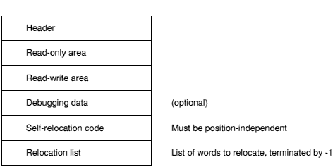
If created with appropriate linker options, an AIF image may relocate itself at load time. Two kinds of self-relocation are supported:
The second kind of self-relocation can only be used if the target system supports an operating system or monitor call which returns the address of the top of available memory. The ARM linker provides a simple mechanism for using a modified version of the self-move code illustrated in Self-Move and Self-Relocation Code, allowing AIF to be easily tailored to new environments.
AIF images support being debugged by the Desktop debugging tool (DDT). Low-level and source-level support are orthogonal, and both, either, or neither kind of debugging support need be present in an AIF image.
For details of the format of the debugging tables see ASD.
References from debugging tables to code and data are in the form of relocatable addresses. After loading an image at its load address these values are effectively absolute. References between debugger table entries are in the form of offsets from the beginning of the debugging data area. Thus, following relocation of a whole image, the debugging data area itself is position independent and may be copied or moved by the debugger.
The layout of a compressed AIF image is as follows:
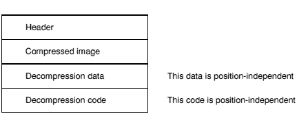
The header is small, fixed in size, and described below. In a compressed AIF image, the header is not compressed.
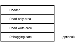
An uncompressed image has the following layout:
Debugging data is absent unless the image has been linked using the linker's -d option and, in the case of source-level debugging, unless the components of the image have been compiled using the compiler's -g option.
The relocation list is a list of byte offsets from the beginning of the AIF header, of words to be relocated, followed by a word containing -1. The relocation of non-word values is not supported.
After the execution of the self-relocation code - or if the image is not self-relocating - the image has the following layout:
At this stage a debugger is expected to copy any debugging data to somewhere safe, otherwise it will be overwritten by the zero-initialised data and/or the heap/stack data of the program. A debugger can seize control at the appropriate moment by copying, then modifying, the third word of the AIF header (see AIF Header Layout).
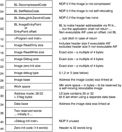
NOP is encoded as MOV r0, r0.
BL is used to make the header addressable via r14 in a position-independent manner, and to ensure that the header will be position-independent. Care is taken to ensure that the instruction sequences which compute addresses from these r14 values work in both 26-bit and 32-bit ARM modes.
Program Exit Instruction will usually be a SWI causing program termination. On systems which lack this, a branch-to-self is recommended. Applications are expected to exit directly and not to return to the AIF header, so this instruction should never be executed. The ARM linker sets this field to SWI 0x11 by default, but it may be set to any desired value by providing a template for the AIF header in an area called AIF_HDR in the first object file in the input list to Link.
Image ReadOnly Size includes the size of the AIF header only if the AIF type is executable (that is, if the header itself is part of the image).
An AIF image is re-startable if, and only if, the program it contains is re-startable (note: an AIF image is not reentrant). If an AIF image is to be re-started then, following its decompression, the first word of the header must be set to NOP. Similarly, following self-relocation, the second word of the header must be reset to NOP. This causes no additional problems with the read-only nature of the code segment: both decompression and relocation code must write to it. On systems with memory protection, both the decompression code and the self-relocation code must be bracketed by system calls to change the access status of the read-only section (first to writable, then back to read-only).
The image debug type has the following meaning:
| 0: | No debugging data are present. |
| 1: | Low-level debugging data are present. |
| 2: | Source level (ASD) debugging data are present. |
| 3: | 1 and 2 are present together. |
All other values of image debug type are reserved to ARM Ltd.
Debug Initialisation Instruction (if used) is expected to be a SWI instruction which alerts a resident debugger that a debuggable image is commencing execution. Of course, there are other possibilities within the AIF framework. The linker sets this field to NOP by default, but it can be customised by providing your own template for the AIF header in an area called AIF_HDR in the first object file in the input list to Link.
The Address mode word (at offset 0x30) is 0, or contains in its least significant byte (using the byte order appropriate to the target):
A value of 0 indicates an old-style 26-bit AIF header.
If the Address mode word has bit 8 set ((address_mode & 0x100) != 0), then the image was linked with separate code and data bases (usually the data is placed immediately after the code). In this case, the word at offset 0x34 contains the base address of the image's data.
The Zero-initialisation code is as follows:
ZeroInit
    NOP                       ; or <Debug Init Instruction>
    SUB     ip, lr, pc        ; base+12+[PSR]-(ZeroInit+12+PSR])
                              ; = base-ZeroInit
    ADD     ip, pc, ip        ; base-ZeroInit+ZeroInit+16
                              ; = base+16
    LDMIB   ip, {r0,r1,r2,r3} ; various sizes
    SUB     ip, ip, #16       ; image base
    LDR     r2, [ip, #48]     ; flags
    TST     r2, #256          ; separate data area?
    LDRNE   ip, [ip, #52]     ; Yes, so get it...
    ADDEQ   ip, ip, r0        ; No, so add + RO size
    ADD     ip, ip, r1        ; + RW size = base of 0-init area
    MOV     r0, #0
    CMPS    r3, #0
00  MOVLE   pc, lr            ; nothing left to do
    STR     r0, [ip],#4
    SUBS    r3, r3, #4
    B       %B00
This code is added to the end of an AIF image by the linker, immediately before the list of relocations (which is terminated by -1). Note that the code is entered via a BL from the second word of the AIF header so, on entry, r14 points to AIFHeader + 8. In 26-bit ARM modes, r14 also contains a copy of the PSR flags.
On entry, the relocation code calculates the address of the AIF header (in a CPU-independent fashion) and decides whether the image needs to be moved. If the image doesn't need to be moved, the code branches to R(elocateOnly).
RelocCode
    NOP                   ; required by ensure_byte_order()
                          ; and used below.
    SUB    ip, lr, pc     ; base+8+[PSR]-(RelocCode+12+[PSR])
                          ; = base-4-RelocCode
    ADD    ip, pc, ip     ; base-4-RelocCode+RelocCode+16 = base+12
    SUB    ip, ip, #12    ; -> header address
    LDR    r0, RelocCode  ; NOP
    STR    r0, [ip, #4]   ; won't be called again on image re-entry
    LDR    r9, [ip, #&2C] ; min free space requirement
    CMPS   r9, #0         ; 0 => no move, just relocate
    BEQ    RelocateOnly
If the image needs to be moved up memory, then the top of memory has to be found. Here, a system service (SWI 0x10) is called to return the address of the top of memory in r1. This is, of course, system specific and should be replaced by whatever code sequence is appropriate to the environment.
    LDR    r0, [ip, #&20]    ; image zero-init size
    ADD    r9, r9, r0        ; space to leave = min free + zero init
    SWI    #&10              ; return top of memory in r1.
The following code calculates the length of the image inclusive of its relocation data, and decides whether a move up store is possible.
    ADR    r2, End           ; -> End
01  LDR    r0, [r2], #4      ; load relocation offset, increment r2
    CMNS   r0, #1            ; terminator?
    BNE    %B01              ; No, so loop again
    SUB    r3, r1, r9        ; MemLimit - freeSpace
    SUBS   r0, r3, r2        ; amount to move by
    BLE    RelocateOnly      ; not enough space to move...
    BIC    r0, r0, #15       ; a multiple of 16...
    ADD    r3, r2, r0        ; End + shift
    ADR    r8, %F02          ; intermediate limit for copy-up
Finally, the image copies itself four words at a time, being careful about the direction of copy, and jumping to the copied copy code as soon as it has copied itself.
02  LDMDB  r2!, {r4-r7}
    STMDB  r3!, {r4-r7}
    CMPS   r2, r8            ; copied the copy loop?
    BGT    %B02              ; not yet
    ADD    r4, pc, r0
    MOV    pc, r4            ; jump to copied copy code
03  LDMDB  r2!, {r4-r7}
    STMDB  r3!, {r4-r7}
    CMPS   r2, ip            ; copied everything?
    BGT    %B03              ; not yet
    ADD    ip, ip, r0        ; load address of code
    ADD    lr, lr, r0        ; relocated return address
Whether the image has moved itself or not, control eventually arrives here, where the list of locations to be relocated is processed. Each location is word sized and is relocated by the difference between the address the image was loaded at (the address of the AIF header) and the address the image was linked at (stored at offset 0x28 in the AIF header).
RelocateOnly
    LDR    r1, [ip, #&28]    ; header + 0x28 = code base set by Link
    SUBS   r1, ip, r1        ; relocation offset
    MOVEQ  pc, lr            ; relocate by 0 so nothing to do
    STR    ip, [ip, #&28]    ; new image base = actual load address
    ADR    r2, End           ; start of reloc list
04  LDR    r0, [r2], #4      ; offset of word to relocate
    CMNS   r0, #1            ; terminator?
    MOVEQ  pc, lr            ; yes => return
    LDR    r3, [ip, r0]      ; word to relocate
    ADD    r3, r3, r1        ; relocate it
    STR    r3, [ip, r0]      ; store it back
    B      %B04              ; and do the next one
End                          ; The list of offsets of locations to
                             ; relocate starts here, terminated by -1
You can customise the self-relocation and self-moving code generated by Link by providing your version of it in an area called AIF_RELOC in the first object file in Link's input list.
Acknowledgement: This design is based on work originally done for Acorn Computers by Topexpress Ltd.
This section specifies the format of symbolic debugging data generated by ARM compilers, which is used by the Desktop debugging tool (DDT) to support high level language oriented, interactive debugging.
For each separate compilation unit (called a section) the compiler produces debugging data, and a special area in the object code (see AOF for an explanation of ARM Object Format, including areas and their attributes). Debugging data are position independent, containing only relative references to other debugging data within the same section, and relocatable references to other compiler-generated areas.
Debugging data areas are combined by the linker into a single contiguous section of a program image. For a description of the linker's principal output format see AIF.
Since the debugging section is position-independent, the debugger can move it to a safe location before the image starts executing. If the image is not executed under debugger control, the debugging data are simply overwritten.
The format of debugging data allows for a variable amount of detail. This potentially allows the user to trade off among memory used, disc space used, execution time, and debugging detail.
Assembly-language level debugging is also supported, though in this case the debugging tables are generated by the linker. If required, the assembler can generate debugging table entries relating code addresses to source lines. Low-level debugging tables appear in an extra section item, as if generated by an independent compilation (see Debugging Data Items in Detail). Low-level and high-level debugging are orthogonal facilities, though DDT allows the user to move smoothly between levels if both sets of debugging data are present in an image.
A debug data area consists of a series of items. The arrangement of these items mimics the structure of the high-level language program itself.
For each debug area, the first item is a section item, giving global information about the compilation, including a code identifying the language, and flags indicating the amount of detail included in the debugging tables.
Each datum, function, procedure, etc., definition in the source program has a corresponding debug data item; these items appear in an order corresponding to the order of definitions in the source. This means that any nested structure in the source program is preserved in the debugging data, and the debugger can use this structure to make deductions about the scope of various source-level objects. Of course, for procedure definitions, two debug items are needed: a procedure item to mark the definition itself, and an endproc item to mark the end of the procedure's body and the end of any nested definitions. If procedure definitions are nested then the procedure-endproc brackets are nested too. Variable and type definitions made at the outermost level, of course, appear outside of all procedure/endproc items.
Information about the relationship between the executable code and source files is collected together and appears as a fileinfo item, which is always the final item in a debugging area. Because of the C language's #include facility, the executable code produced from an outer-level source file may be separated into disjoint pieces interspersed with that produced from the included files. Therefore, source files are considered to be collections of 'fragments', each corresponding to a contiguous area of executable code, and the fileinfo item is a list with an entry for each file, each in turn containing a list with an entry for each fragment. The fileinfo field in the section item addresses the fileinfo item itself. In each procedure item there is a 'fileentry' field, which refers to the file-list entry for the source file containing the procedure's start; there is a separate one in the endproc item because it may possibly not be in the same source file.
The ARM can be configured to use either a little-endian memory system (the least significant byte of each 4-byte word has the lowest address), or a big-endian memory system (the most significant byte of each 4-byte word has the lowest address).
In general, the code to be generated varies according to the endian-ness (or byte-sex) of the target. The linker has insufficient information to change an object file's byte sex, so object files are encoded using the byte order of the intended target, independently of the byte order of the host system on which the compiler or assembler runs. The linker accepts inputs having either byte order, but rejects mixed sex inputs, and generates its output using the same byte order.
This means that producers of debugging tables must be prepared to generate them in either byte order, as required. In turn, this requires definitions to be very clear about when a 4-byte word is being used (which will require reversal on output or input when cross-sex compiling or debugging), and when a sequence of bytes is being used (which requires no special treatment provided it is written and read as a sequence of bytes in address order).
Several of the debugging data items (e.g. procedure and variable) have a type word field to identify their data type. This field contains, in the most significant 24 bits, a code to identify a base type, and in the least significant 8 bits, a pointer count:
| 0 | to denote the type itself |
| 1 | to denote a pointer to the type |
| 2 | to denote a pointer to a pointer to... |
| etc. | |
For simple types the code is a positive integer as follows, (all codes are decimal):
| void | 0 | |
| signed integers | ||
| single byte | 10 | |
| half-word | 11 | |
| word | 12 | |
| unsigned integers | ||
| single byte | 20 | |
| half-word | 21 | |
| word | 22 | |
| floating point | ||
| float | 30 | |
| double | 31 | |
| long double | 32 | |
| complex | ||
| single complex | 41 | |
| double complex | 42 | |
| functions | ||
| function | 100 | |
For compound types (arrays, structures, etc.) there is a special kind of debug data item (array, struct, etc.) to give details such as array bounds and field types. The type code for compound types is negative, the negation of the (byte) offset of the debug item from the start of the debugging area.
If a type has been given a name in a source program, it will give rise to a type debugging data item which contains the name and a type word as defined above. If necessary, there will also be a debugging data item, such as an array or struct item, to define the type itself. In that case, the type word will refer to this item.
Set types in Pascal are not treated in detail: the only information recorded for them is the total size occupied by the object in bytes. Neither are Pascal file variables supported by the debugger, since their behaviour under debugger control is unlikely to be helpful to the user.
FORTRAN character types are supported by special kinds of debugging data item, the format of which is specific to each FORTRAN compiler.
Several of the debugging data items have a sourcepos field to identify a position in the source file. This field contains a line number and character position within the line packed into a single word. The most significant 10 bits encode the character offset (0-based) from the start of the line and the least-significant 22 bits give the line number.
The first word of each debugging data item contains the byte length of the item (encoded in the most significant 16 bits), and a code identifying the kind of item (in the least significant 16 bits). The defined codes are:
| 1 | section |
| 2 | procedure/function definition |
| 3 | endproc |
| 4 | variable |
| 5 | type |
| 6 | struct |
| 7 | array |
| 8 | subrange |
| 9 | set |
| 10 | fileinfo |
| 11 | contiguous enumeration |
| 12 | discontiguous enumeration |
| 13 | procedure/function declaration |
| 14 | begin naming scope |
| 15 | end naming scope |
The meaning of the second and subsequent words of each item is defined below.
If a debugger encounters a code it does not recognise, it should use the length field to skip the item entirely. This discipline allows the debugging tables to be extended without invalidating existing debuggers.
Where items include a string field, the string is packed into successive bytes beginning with a length byte, and padded at the end to a word boundary with 0 bytes. The length of a string is in the range [0..255] bytes.
Where an item contains a field giving an offset in the debugging data area (usually to address another item), this means a byte offset from the start of the debugging data for the whole section (in other words, from the start of the section item).
When the same structure is used to map debugging data in memory, an offset field may be used to hold a pointer to another debug item in memory, rather than the offset of it in the debug area.
A section item is the first item of each section of the debugging data. After its code and length word it contains the fields listed below. First there are 4 flag bytes:
| lang | a byte identifying the source language |
| flags | a byte describing the level of detail |
| unused | |
| asdversion | a byte version number of the debugging data |
The following language byte codes are defined:
| LANG_NONE | 0 | Low-level debugging data only |
| LANG_C | 1 | C source level debugging data |
| LANG_PASCAL | 2 | Pascal source level debugging data |
| LANG_FORTRAN | 3 | FORTRAN-77 source level debugging data |
| LANG_ASM | 4 | ARM Assembler line number data |
All other codes are reserved to ARM.
The flags byte uses the following mask values:
| 1 | debugging data contains line-number information |
| 2 | debugging data contains information about top-level variables |
| 3 | both of the above |
The asdversion byte should be set to 3, the version of this definition.
The flag bytes are followed by the following word-sized fields:
| codestart | address of first instruction in this section |
| datastart | address of start of static data for this section |
| codesize | byte size of executable code in this section |
| datasize | byte size of the static data in this section |
| fileinfo | offset in the debugging area of the fileinfo item for this section (0 if no fileinfo item present) |
| debugsize | total byte length of debug data for this section |
| name or nsyms | string or integer (the first byte of string is the string's length, followed by a non-NULL-terminated string of characters with NULL padding up to the next word boundary) |
codestart and datastart are addresses, relocated by the linker. The fileinfo field, nominally an offset, is also used as a pointer when this structure is mapped in memory. The fileinfo field is 0 if no source file information is present.
The name field contains the program name for Pascal and FORTRAN programs. For C programs it contains a name derived by the compiler from the root file name (notionally a module name). In each case, the name is similar to a variable name in the source language. For a low-level debugging section (language = 0), the field is treated as a 4 byte integer giving the number of symbols following.
For linker-generated low-level debugging data, the fields have the following values:
| language | 0 |
| codestart | Image$$RO$$Base |
| datastart | Image$$RW$$Base |
| codesize | Image$$RO$$Limit - Image$$RO$$Base |
| datasize | Image$$RW$$Limit - Image$$RW$$Base |
| fileinfo | 0 |
| nsyms | number of symbols in the following debugging data |
| debugsize | total size of the low-level debugging data including the size of this section item |
For linker-generated low-level debugging data, the section item is followed by nsyms symbol items, each consisting of 2 words:
| sym | flags + byte offset in string table of symbol name |
| value | the value of the symbol |
sym encodes an index into the string table in the 24 least significant bits, and the following flag values in the 8 most significant bits:
| ASD_GLOBSYM | 0 | if the symbol is absolute |
| ASD_ABSSYM | 0x01000000L | if the symbol is global |
| ASD_TEXTSYM | 0x02000000L | if the symbol names code |
| ASD_DATASYM | 0x04000000L | if the symbol names data |
| ASD_ZINITSYM | 0x06000000L | if the symbol names 0-initialised data |
Note that the linker reduces all symbol values to absolute values, so that the flag values record the history, or origin, of the symbol in the image.
Immediately following the symbol table is the string table, in standard AOF format. It consists of:
The length word includes the size of the length word, so no offset into the string table is less than 4. The end of the string table is padded with NULs to the next word boundary (so the length is a multiple of 4).
A procedure item appears once for each procedure or function definition in the source program. Any definitions within the procedure have their related debugging data items between the procedure item and its matching endproc item. After its code and length field, a procedure item contains the following word-sized fields:
| type | the return type if this is a function, else 0 (see Representation of Data Types) |
| args | the number of arguments |
| sourcepos | the source position of the procedure's start (see Representation of Data Types) |
| startaddr | address of 1st instruction of procedure prologue |
| entry | address of 1st instruction of the procedure body (see note below) |
| endproc | offset of the related endproc item (in file) or pointer to related endproc item (in memory) |
| fileentry | offset of the file list entry for the source file (in file) or a pointer to it (in memory) |
| name | string (the first byte of string is the string's length, followed by a non-NULL-terminated string of characters with NULL padding up to the next word boundary) |
The entry field addresses the first instruction following the procedure prologue. That is, the first address at which a high-level breakpoint could sensibly be set. The startaddr field addresses the start of the prologue. That is, the instruction at which control arrives when the procedure is called.
A label in a source program is represented by a special procedure item with no matching endproc, (the endproc field is 0 to denote this). Pascal and FORTRAN numerical labels are converted by their respective compilers into strings prefixed by $n.
For FORTRAN77, multiple entry points to the same procedure each give rise to a separate procedure item, all of which have the same endproc offset referring to the unique, matching endproc item.
An endproc item marks the end of the debugging data items belonging to a particular procedure. It also contains information relating to the procedure's return. After its code and length field, an endproc item contains the following word-sized fields:
| sourcepos | position in the source file of the procedure's end (see Representation of Source File Positions) |
| endpoint | address of the code byte after the compiled code for the procedure |
| fileentry | offset of the file-list entry for the procedure's end (in file) or a pointer to it (in memory) |
| nreturns | number of procedure return points (may be 0) |
| retaddrs | array of addresses of procedure return code |
If the procedure body is an infinite loop, there will be no return point, so nreturns will be 0. Otherwise each member of retaddrs should point to a suitable location at which a breakpoint may be set 'at the exit of the procedure'. When execution reaches this point, the current stack frame should still be for this procedure.
A variable item contains debugging data relating to a source program variable, or a formal argument to a procedure (the first variable items in a procedure always describe its arguments). After its code and length field, a variable item contains the following word-sized fields:
| type | type of this variable (see Representation of Data Types) |
| sourcepos | the source position of the variable (see Representation of Source File Positions) |
| storageclass | a word encoding the variable's storage class |
| location | see explanation below |
| name | string (the first byte of string is the string's length, followed by a non-NULL-terminated string of characters with NULL padding up to the next word boundary) |
The following codes define the storage classes of variables:
| 1 | external variables (or FORTRAN common) |
| 2 | static variables private to one section |
| 3 | automatic variables |
| 4 | register variables |
| 5 | Pascal 'var' arguments |
| 6 | FORTRAN arguments |
| 7 | FORTRAN character arguments |
The meaning of the location field of a variable item depends on the storage class; it contains:
No account is taken of variables which ought to be addressed by +ve offsets from the stack-pointer rather than -ve offsets from the frame-pointer.
The sourcepos field is used by the debugger to distinguish between different definitions having the same name (e.g. identically named variables in disjoint source-level naming scopes such as nested blocks in C).
A type item is used to describe a named type in the source language (e.g. a typedef in C). After its code and length field, a type item contains two word-sized fields:
| type | a type word (see Representation of Data Types) |
| name | string (the first byte of string is the string's length, followed by a non-NULL-terminated string of characters with NULL padding up to the next word boundary) |
A struct item is used to describe a structured data type (e.g. a struct in C or a record in Pascal). After its code and length field, a struct item contains the following word-sized fields:
| fields | the number of fields in the structure |
| size | total byte size of the structure |
| fieldtable... | an array of fields struct field items |
Each struct field item has the following word-sized fields:
| offset | byte offset of this field within the structure |
| type | a type word (see Representation of Data Types) |
| name | string (the first byte of string is the string's length, followed by a non-NULL-terminated string of characters with NULL padding up to the next word boundary) |
Union types are described by struct items in which all fields have 0 offsets.
C bit fields are not treated in full detail: a bit field is simply represented by an integer starting on the appropriate word boundary (so that the word contains the whole field).
An array item is used to describe a one-dimensional array. Multi-dimensional arrays are described as 'arrays of arrays'. Which dimension comes first is dependent on the source language (which is different for C and FORTRAN). After its code and length field, an array item contains the following word-sized fields:
| size | total byte size of the array |
| flags | see below |
| basetype | a type word (see Representation of Data Types) |
| lowerbound | constant value or location of variable |
| upperbound | constant value or location of variable |
If the size field is zero, debugger operations affecting the whole array, rather than individual elements of it, are forbidden.
The following mask values are defined for the flags field:
| ARRAY_UNDEF_LBOUND | 1 | lower bound is undefined |
| ARRAY_CONST_LBOUND | 2 | lower bound is a constant |
| ARRAY_UNDEF_UBOUND | 4 | upper bound is undefined |
| ARRAY_CONST_UBOUND | 8 | upper bound is a constant |
| ARRAY_VAR_LBOUND | 16 | lower bound is a variable |
| ARRAY_VAR_UBOUND | 32 | upper bound is a variable |
A bound is described as undefined when no information about it is available.
A bound is described as constant when its value is known at compile time. In this case, the corresponding bound field gives its value.
If a bound is described as variable, the offset field identifies a variable debug item describing the location containing the bound. In a debug area in an object file, the offset field contains the offset from the start of the debug area to the variable item; in memory it contains a pointer to the corresponding variable item. Note that a variable item may be used to describe a location known to the compiler, which need not correspond to a source language variable.
A subrange item is used to describe a subrange typed in Pascal. It also serves to describe enumerated types in C, and scalars in Pascal (in which case the base type is understood to be an unsigned integer of appropriate size). After its code and length field, a subrange item contains the following word-sized fields:
| sizeandtype | see below |
| lb | low bound of subrange |
| hb | high bound of subrange |
The sizeandtype field encodes the byte size of container for the subrange (1, 2 or 4) in its least significant 16 bits, and a simple type code (see Representation of Data Types) in its most significant 16 bits. The type code refers to the base type of the subrange.
For example, a subrange 256..511 of unsigned short might be held in 1 byte.
A set item is used to describe a Pascal set type. Currently, the description is only partial. After its code and length field, a set item consists of a single word:
| size | byte size of the object |
An enumeration item describes a Pascal or C enumerated type. After its code and length word, the description of a 'contiguous enumeration' contains the following word-sized fields
| type | a type word describing the type of the container for the enumeration (see Representation of Data Types) |
| count | the cardinality of the enumeration |
| base | the first (lowest) value (may be -ve) |
| nametable | a character array containing 'count' names (see Text Names in Items) (the first byte of name is the name's length, followed by a non-NULL-terminated string of characters with NULL padding up to the next word boundary) |
The description of a discontiguous enumeration (such as the C enumeration enum bits {bit0=1, bit1=2, bit2=4, bit3=8, bit4=16}) contains the following fields after its code and length word:
| type | as above |
| count | as above |
| nametable | a table of count (value, name) pairs |
Each nametable entry has the following format (which is variable in length):
| val | a word describing the enumerated value (1/2/4/8/16 in the example) |
| name | the name of the enumerated element (may be several words long) (the first byte of name is the name's length, followed by a non-NULL-terminated string of characters with NULL padding up to the next word boundary) |
After its code and length word, a function declaration item contains the following fields:
| type | a type word (see Representation of Data Types) describing the return type of the function or procedure |
| argcount | the number of arguments to the function |
| args | a sequence of argcount argument description items |
Each argument description item contains the following:
| type | a type word (see Representation of Data Types) describing the type of the argument |
| name | the name of the argument (may be several words) (the first byte of name is the name's length, followed by a non-NULL-terminated string of characters with NULL padding up to the next word boundary) |
An argument descriptor need not be named; in this case the length of the name is zero, and the name field is a single zero word.
These debug items are used to mark the beginning and end of a naming scope. They must be properly nested in the debug area.
In each case, after the code and length word, there is one word-sized field:
| codeaddress | address of the start/end of scope (determined by the code word) |
A fileinfo item appears once per section, after all other debugging data items. If the fileinfo item is too large for its length to be encoded in 16 bits, its length field must be written as 0 (since this is the last item in a section and the section header contains the length of the whole section, the length field is strictly redundant.
Each source file is described by a sequence of fragments. Each fragment describes a contiguous region of the file, within which the addresses of compiled code increase monotonically with source file position. The order in which fragments appear in the sequence is not necessarily related to the source file positions to which they refer.
Note that for compilations which make no use of the #include facility, the list of fragments may have only one entry, and all line-number information can be contiguous.
After its code and length word, the fileinfo item is a sequence of file entry items with the following format:
| len | length of this entry in bytes (including the length of the following fragments) |
| date | date and time when the file was last modified may be 0, indicating not available, or unused) |
| filename | string (or "" if the name is not known) (the first byte of string is the string's length, followed by a non-NULL-terminated string of characters with NULL padding up to the next word boundary) |
| fragment data | see below |
If present, the date field contains the number of seconds since the beginning of 1970 (the Unix date origin).
Following the final file entry item, is a single 0 word marking the end of the sequence.
The fragment data is a word giving the number of following fragments followed by a sequence of fragment items:
| n | number of fragments following |
| fragments... | n fragment items |
Each fragment item consists of 5 words, followed by a sequence of byte pairs and half word pairs, formatted as follows:
| size | length of this fragment in bytes (including length of following lineinfo items) |
| firstline | linenumber |
| lastline | linenumber |
| codestart | pointer to the start of the fragment's executable code |
| codesize | byte size of the code in the fragment |
| lineinfo... | a variable number of bytes matching line numbers to code addresses |
Each lineinfo item describes a source statement and consists of a pair of (unsigned) bytes, possibly followed by a two or three (unsigned) half words, (each half word has the byte ordering appropriate to the target memory system's endian-ness or byte sex).
The short form (pair of bytes) lineinfo item is as follows:
| codeinc | # bytes of code generated by this statement |
| lineinc | # source space occupied by this statement |
lineinc describes how to calculate the source position (line, column) of the next statement from the source position of this one:
If lineinc is in the range 0  and < 64, the new position is (line+lineinc,1).
If lineinc  64, the new position is (line, column+lineinc -64).
The number of bytes of code generated for a statement may be zero, provided the line increment is non-zero (such an item may describe a block end or block start, for example).
It is not possible to describe a statement which generates no code and no line number increment, as that encoding is used as an escape to the long form lineinfo items described below.
If codeinc is greater than 255, or lineinc is required to describe a line number change greater than 63 or a column change greater than 191, then both bytes are written to describe 0 increments, and the real values are given in the following two or three (unsigned) half words. (Note that there are two ways to describe 0 increments: 0 lines and 0 columns, which serves to discriminate between the two half word and three half word forms). If the starting column for the next statement is 1, the two half word form is used, which in effect is a triple of half words as follows:
| zero | 2 zero bytes |
| lineinc | # source lines occupied by this statement |
| codeinc | # bytes of code generated by this statement |
Note that the order of the lineinc and codeinc half words is the reverse of the corresponding bytes.
If the starting column for the next statement is not 1, the three half word form is used, which in effect is a quadruple of half words, as follows:
| codeinc = 0, lineinc = 64 | |
| lineinc | # source lines occupied by this statement |
| codeinc | # bytes of code generated by this statement |
| newcol | starting column for the next statement |
Note as above that the order of the lineinc and codeinc half words is the reverse of the corresponding bytes. Note also that the column item here is the absolute column number for the next statement, and not an increment as in the two byte form.
(This encoding of lineinfo items is an incompatible change from the previous format (version 2): in that format, lineinc in a two byte lineinfo item always describes a line increment, and accordingly, there is no four half word form. Programs interpreting asd tables should interpret lineinfo items differently according to the table format in the section item.)