
|
www.riscos.com Technical Support: |
ADFS is the Advanced Disc Filing System. It is a module that, together with FileSwitch and FileCore, provides a disc-based filing system.
Most of the facilities that you will use with ADFS are in fact provided by FileCore and FileSwitch, and you should read the chapters on those modules (on FileSwitch and FileCore respectively) in conjunction with this one.
ADFS is a module that provides the hardware-dependent part of a disc-based filing system. It uses FileCore, and so conforms to the standards for a module that does so; see the chapter entitled FileCore for details.
It provides:
Except for the low-level entry points and routines (which are for the use of FileCore only) all of these are described below.
For a full summary of 'perfect' ADFS formats, see from Disc formats onwards of the FileCore.
If you are running a site with a mixture of 1772-equipped 'old' machines and 710/711-equipped 'newer' machines, we recommend that you format all discs on the latter.
On old machines, D and E format discs have the sectors offset between sides for speed optimisation. The 710/711 cannot format discs in this manner, and may run slow when accessing such discs. By formatting discs on newer machines, they will run at the same speed on every machine, albeit some 5% slower than discs with offset sectors can run on older machines.
Likewise, we recommend that any software you ship uses discs that do not offset sectors between sides (ie the discs are formatted on a newer machine).
If you wish to vary the format of a disc to provide software protection, you should follow the guidelines below. This will ensure that your discs are reliably readable and quick to load on all RISC OS machines, current or planned.
Disc formats should conform to the specifications in the FileCore, with some exceptions. You may:
You may not:
The last point prohibits such common practices as reading a 1k sector with a 2k read (to recover inter-sector data), or reading a track with a different head number to that in the sector ID (which works with a 1772, but fails with the 710/711 used on machines such as the A5000).
Limitations of disc controllers place further restrictions on using 128 byte sectors:
For the purposes of formatting, the speed stability of disc drives will be assumed to be 1.5%.
Drives which fit into the following specification will never have a data overrunning:
| Variation in speed: | ±1.5% |
| Min. Write to read changeover time: | 696 ![[MU]](../symbols/entities/956.png) S (2Meg mode) (43 bytes) S (2Meg mode) (43 bytes)1300 S (1Meg mode) (40 bytes)(values for one particular drive) |
| Track length (nominal) | 12500 bytes (2Meg mode) 6250 bytes (1Meg mode) |
| Assuming the drive is always running fast gives an actual workable track length of: | 12312 bytes (2Meg mode) 6156 bytes (1Meg mode) |
If evaluating the total byte usage of the given formats gives a number less than the minimum track length, then that format fits and will be reliable.
Here are the parameters of the parts of a track:
| (soft) Index mark | 96 bytes | |
| Minimum gap 4 | 30 bytes (2Meg mode) 40 bytes (1Meg mode) | |
| Sector overhead | 62 bytes (includes gap 2 and pre-ambles): | |
| Bytes | Use | |
|---|---|---|
| 12 | 00-bytes (preamble) | |
| 3 | A1-bytes | |
| 1 | FE-ID of address field | |
| 1 | Track | |
| 1 | Side | |
| 1 | Sector | |
| 1 | Length | |
| 1 | CRC 1 | |
| 1 | CRC 2 | |
| 22 | 4e-gap 2 | |
| 12 | 00-bytes (preamble) | |
| 3 | A1-bytes | |
| 1 | FB-ID of data field | |
| n | (data - not included in sector overhead) | |
| 1 | CRC 1 | |
| 1 | CRC 2 | |
| 62 | Total | |
Plugging the numbers in gives:
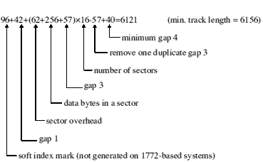
Byte usage for a track: L format
1772-based system without index mark:
Byte usage for a track: D and E formats (no index mark)
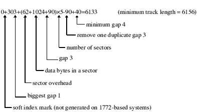
710/711-based system with index mark (gap 1 forced to 50 bytes by the 710/711):
Byte usage for a track: D and E formats (index mark)
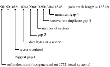
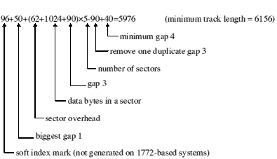
Byte usage for a track: F format
In checking the gap 3 value assuming worst case drive speed variation:
This gives an overhead over the data of 40 bytes.
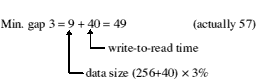
Minimum Gap3 size: L format

Minimum Gap3 size: D and E formats
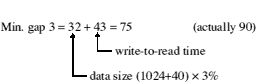
Minimum Gap3 size: F format
Working the calculations the other way round gives the worst case values for the write-to-read time for a drive whose speed variation is 1.5%:
Worst write to read time: L format
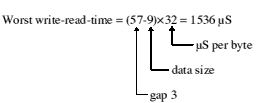
Worst write to read time: D and E formats
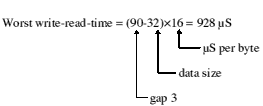
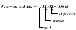
Worst write to read time: F format
These are the limit parameters for the two floppy controllers ADFS supports:
| Controller | 1772 | 710/711 |
|---|---|---|
| Sectors per track, low | 1 | 0 |
| Sectors per track, high | 240 | 255 |
| Track, low | 0 | 0 |
| Track, high | 240 | 255 |
| Log2 (sector length), low | 7 | 7 |
| Log2 sector length, high | 10 | 14 |
| Sector number, low (formatting) | 0 | 0 |
| Sector number, high (formatting) | 255 | 255 |
| Format fill values always allowed | 00-&F4, &FF | 00-&FF |
| Formatting with ID mark | optional | forced |
| Gap3 maximum length (formatting) | track length | 255 |
(These values are extracted from the 1772 data sheet)
| Dens | gap1 | gap3 | ~gap4 |
|---|---|---|---|
| FM |  16 16
| 10
| 16
|
| MFM | 32
| 24
| 16
|
Evaluation of 'does it fit' is:
Low track length - gap1 + gap3 - (secsize + SecOvrhead + gap3)×secs min. gap4
If 'no', does it fit using minimum gap1 and minimum gap3?
Does the side/side skew invalidate gap4?
The range of floppy drives supported by the 82C710/82C711 driver is considerably wider than that supported by older drivers. In general any PC/XT/AT compatible 31/2"/51/4" 40/80 track drive can be used. The following minimal requirements will ensure optimal performance:
500Kbps).
The following table illustrates the combination of motor on and drive select signals supplied for various drive selections:
| Drive Selected | /DS0 | /DS1 | /ME0 | /ME1 |
|---|---|---|---|---|
| 0 | L | H | L | H |
| 1 | H | L | H | L |
| 2 | H | H | H | L |
| 3 | H | H | L | L |
| None | H | H | H | H |
Drives 2 and 3 do not result in any drive select line being asserted, but can be decoded by an external decoder.
To help you understand the floppy disc drive interface, this section discusses further the function and use of each of the interface signals.
All interface signals are open-collector, and therefore require a pull-up resistor of nominally 1k![[OMEGA]](../symbols/entities/937.png) FOR 31/2" SYSTEMS OR 150 IN OLDER 51/4" systems. The pull-up should be present in one place only - either on the drive furthest from the controller (for outputs), or on the controller (for inputs).
FOR 31/2" SYSTEMS OR 150 IN OLDER 51/4" systems. The pull-up should be present in one place only - either on the drive furthest from the controller (for outputs), or on the controller (for inputs).
Due to the nature of open collector signals no damage will occur if several outputs drive one signal; thus it is safe, for instance, to connect 'motor on' to 'Sel2' and force motor on true whenever Sel2 is asserted.
All signals are active (asserted) low, ie active when at 0 Volts. Inputs are only valid when a drive is selected.
Used to select the drive; only one should be active at any given time. Most 'AT' compatible drives assume only drive select 1 will ever be asserted, since there is a physical twist in the cable to determine the actual drive number.
Asserted to turn the drive motor on (and load the head on 51/4" drives). A period of 0.5 seconds (1 second for drives 2 and 3) is allowed before any data transfer occurs to allow the drive motor to come up to speed.
Asserted to select the under surface of a disc
Asserted to step the head in the direction given by DirIn. Also used to reset DiscChanged. A period of 15-20 ms is required to allow for head settling after any movement.
Asserted to move the head inwards (to the centre) during head movements.
Data from the controller to be written to disc.
Qualifies WriteData. Asserted prior to and after WriteData is true to enable recording of the data.
Informs the drive of the current data rate. Asserted for 500Kbps and 1Mbps operations (1.6 and 3.2 Mbyte formats). Normally on pin2, some drives may require an inverted signal if intended for use with PS/2 systems.
Asserted by the drive when the head is on track 0.
Asserted by the drive when the disc is write protected.
Data stream read from the disc.
Index pulses are produced every disc revolution (200mS). The 82C710/82C711 driver uses the presence of index pulses to detect a disc in. If a drive does not support 'DiscChanged' then in order to function with the 82C710 /82C711 driver it must inhibit index pulses with the drive empty; this is the normal situation. Performance is improved if index pulses are not masked during seek or motor startup. Index pulses must be present within 900mS (1400mS for drives 2 and 3) of asserting drive select/motor on, otherwise the drive will be deemed to be empty.
This signal is normally available on pin34 or pin2 and when asserted indicates that the disc in the selected drive has been changed. Neither the 1772 nor the 82C710/82C711 driver require DiscChanged in order to function, but give better performance if available. The signal must never be asserted if non-functional.
Dependent upon drive type the disc changed signal may either be reset by issuing a step pulse (82C710/82C711 driver) and/or by asserting the disc changed reset signal (1772 driver). If DiscChanged is reset by 'step', the wimp polling period is set to 1 per second; otherwise it is set to 10 times per second.
Often available on 51/4" drives, and available from drives for A440/540 series machines on pin34. Asserted when the drive is ready for read/write operations. This feature is required by the 1772 driver. If not present, Ready must be tied low for the driver to function.
Disc errors are errors returned by the controller. The following sections list the disc error codes returned for all controllers currently used in RISC OS computers.
1772 disc error codes are basically the error codes returned in the status byte of the 1772. These are the status bits in that status byte:
| Bit | Name | Meaning |
|---|---|---|
| 7 | FdcMotorOnBit | |
| 6 | WProtBit | Write protect (translated to disc write protected error) |
| 5 | WFaultBit | Write fault |
| 4 | RnfBit | Record not found |
| 3 | CrcBit | CRC error |
| 2 | LostBit | Lost data |
| 1 | Track0Bit | |
| 0 | BusyBit |
So, disc error 8 is a CRC error
ST506 disc error codes are the error codes returned by the HD63463 (ST506) controller shifted right by 2 bits, which gives:
| Value | Name | Meaning |
|---|---|---|
| &01 | ABT | Command abort has been accepted |
| &02 | IVC | Invalid command |
| &03 | PER | Command parameter error |
| &04 | NIN | Head positioning, disc access, or drive check command before SPC has been issued |
| &05 | RTS | TST command after SPC command |
| &06 | NUS | USELD for a selected drive has not been returned |
| &07 | WFL | Write fault (WFLT) has been detected on the ST506 interface |
| &08 | NRY | Ready signal has been negated |
| &09 | NSC | Seek complete (SCP) wasn't returned before timeout |
| &0A | ISE | SEK, or disc access command issued during a seek |
| &0B | INC | Next cylinder address greater than number of cylinders |
| &0C | ISR | Invalid step rate: highest-speed seek specified in normal seek mode. |
| &0D | SKE | SEK or disc access command issued to drive with seek error |
| &0E | OVR | Data overrun (memory slower than drive) |
| &0F | IPH | Head address greater than number of heads |
| &10 | DEE | Error Correction Code (ECC) detected an error |
| &11 | DCE | CRC error in data area |
| &12 | ECR | ECC corrected an error |
| &13 | DFE | Fatal ECC error in data area |
| &14 | NHT | In CMPD command data mismatched from host and disc |
| &15 | ICE | CRC error in ID field (not generated for ST506) |
| &16 | TOV | ID not found within timeout |
| &17 | NIA | ID area started with an improper address mark |
| &18 | NDA | Missing address mark |
| &19 | NWR | Drive write protected |
IDE disc errors are, where possible, mapped onto a similar error from an ST506 - in which case the name of the ST506 error is shown below. Other IDE disc errors are given error codes outside the range used by the ST506:
| Value | Name | Meaning |
|---|---|---|
| &02 | IVC | command aborted by controller |
| &07 | WFL | write fault |
| &08 | NRY | drive not ready |
| &09 | NSC | track 0 not found |
| &13 | DFE | uncorrected data error |
| &16 | TOV | sector id field not found |
| &17 | NIA | bad block mark detected |
| &18 | NDA | no data address mark |
| &20 | no DRQ when expected | |
| &21 | drive busy when commanded | |
| &22 | drive busy on command completion | |
| &23 | controller did not respond within timeout | |
| &24 | unknown code in error register |
710/711 disc error codes are the error codes returned by the (functionally equivalent) 82C710 and 82C711 controllers, which are:
R0 = pointer to format specification string (null terminated)
R1 = &6B (reason code)
All registers preserved (if not claimed)
If claimed:
R0 preserved
R1 = 0
R2 = SWI number to call to obtain raw disc format information
R3 = parameter in R3 to use when calling disc format SWI
R4 = SWI number to call to lay down a disc structure
R5 = parameter in R0 to use when calling disc structure SWI
This call is issued by a handler of discs (such as ADFS) to find how to initialise a disc to a specified format. The format specification string is the same as the format parameter specified in the *Format command (see *Format).
You should claim this call if your module recognises the format specification string as one that you support. If you do not recognise the format - or if you don't support disc formats at all - you should pass the call on with all registers preserved.
For an example of a call used to obtain raw disc format information, see DOSFS_DiscFormat. Similarly, for an example of a call used to lay down a disc structure, see DOSFS_LayoutStructure.
R0 = 0
R1 = &6C (reason code)
If no error occurred whilst displaying the help:
R0, R1 preserved to pass on
If an error occurred whilst displaying the help:
R0 = pointer to error block
R1 = 0 to claim
This service call is issued when the user requests help on the available formats (eg types *Help Format). Your module should list the formats it will recognise in response to Service_IdentifyFormat. The list should be displayed one format per line in this format:
format - description
Where format is the text as recognised by Service_IdentifyFormat, and description is a description of the format. For example:
F - 1600K, 77 entry directories, new map, Archimedes ADFS 2.50 and above.
DOS/Q - 1.44M, MS-DOS 3.20, 3.5" high density disc
You should display the list using OS_WriteC or a derivative of that (eg OS_Write0, OS_WriteS etc).
See FileCore_DiscOp
See FileCore_DiscOp
Interrupt status is undefined
Fast interrupts are enabled
Processor is in SVC mode
Not defined
This SWI calls FileCore_DiscOp, after first setting R8 to point to the FileCore instantiation private word for ADFS.
This call is functionally identical to FileCore_DiscOp.
None
Sets the address of an alternative ST506 hard disc controller
R2 = address of alternative hard disc controller
R3 = address of poll location for IRQ/DRQ
R4 = bits for IRQ/DRQ
R5 = address to enable IRQ/DRQ
R6 = bits to enable IRQ/DRQ
--
Interrupt status is undefined
Fast interrupts are enabled
Processor is in SVC mode
Not defined
This call sets up the address of the ST5056 hard disc controller to be used by the ADFS. For instance, an expansion card can supply an alternative controller to the one normally used. The controller must be an HD63463 (or compatible).
The polling and interrupt sense is done using:
LDRB   Rn, [poll location]
TST    Rn, [poll bits]
The IRQ/DRQ must be 1 when active.
None
None
See FileCore_Drives
See FileCore_Drives
Interrupt status is undefined
Fast interrupts are enabled
Processor is in SVC mode
Not defined
This SWI calls FileCore_Drives, after first setting R8 to point to the FileCore instantiation private word for ADFS.
This call is functionally identical to FileCore_Drives.
None
Interrupt status is undefined
Fast interrupts are enabled
Processor is in SVC mode
Not defined
This SWI calls FileCore_FreeSpace, after first setting R8 to point to the FileCore instantiation private word for ADFS.
This call is functionally identical to FileCore_FreeSpace.
None
R0 = mask of bits to change
R1 = new values of bits to change
R0 preserved
R1 = R0 AND entry value of R1
R2 = old value of retry word
R3 = new value of retry word
Interrupt status is undefined
Fast interrupts are enabled
Processor is in SVC mode
Not defined
This call sets the number of retries used by writing to the retry word. The format of this word is:
| Byte | Number of retries for |
|---|---|
| 0 | hard disc read/write sector |
| 1 | floppy disc read/write sector |
| 2 | floppy disc mount (per copy of the disc map) |
| 3 | verify after *Format, before sector is considered a defect |
The new value is calculated as follows:
None
None
Interrupt status is undefined
Fast interrupts are enabled
Processor is in SVC mode
Not defined
This SWI calls FileCore_DescribeDisc, after first setting R8 to point to the FileCore instantiation private word for ADFS.
This call is functionally identical to FileCore_DescribeDisc.
None
Vets a disc format structure for achievability with the available hardware
R0 = pointer to disc format structure to be vetted
R1 = parameter previously passed by ADFS in R2 to ImageFS_DiscFormat (ie drive number)
R0, R1 preserved
Interrupt status is undefined
Fast interrupts are enabled
Processor is in SVC mode
Not defined
This call vets the given disc format structure for achievability with the available hardware. ADFS updates the disc format structure with values that it can actually achieve with the hardware available. For example the only fill byte value available when formatting might be 0, but the requested value may be &4E, hence 0 would be filled in as the fill byte value.
If ADFS cannot sensibly downgrade the parameters given in the disc format structure, it will generate an error.
This call is typically made by FileCore or by the image filing system ImageFS,
in response to ADFS calling FileCore_DiscFormat or ImageFS_DiscFormat (eg DOSFS_DiscFormat) respectively.
This call is not available under RISC OS 2.
The value in R1 is used to pass enough information on the hardware on which the format is to take place for the disc format structure to be vetted. ADFS uses the drive number for this; other handlers of discs may pass different information if they implement a VetFormat SWI.
None
For internal use only
This call is for internal use only. It is not available under RISC OS 2.
R0 = drive number (0 - 7)
R0 = controller type
 disc not present 1772 710/711 ST506 IDE
Flags corrupted
Interrupt status is undefined
Fast interrupts are enabled
Processor is in SVC mode
Not defined
This call returns the controller type of the given drive.
This call is not available under RISC OS 2.
None
None
R0 = reason code:
read drive spin status set drive autospindown control drive spin directly without affecting autospindownR1 = drive
R2 = drive autospindown, if R0 = 1:
= 0 disable autospindown and spinup drive
![[NOT EQUAL]](../symbols/entities/8800.png) 0 set autospindown to (R2 × 5) seconds
0 set autospindown to (R2 × 5) seconds
or action to take, if R0 = 2:
= 0 spin down immediately
0 spin up immediately
R2 = drive spin status, if R0 = 0 on entry:
drive is not spinning 0 drive is spinning
Interrupt status is undefined
Fast interrupts are enabled
Processor is in SVC mode
Not defined
This call controls the power-saving features of the ADFS system.
It can be dangerous to use this call on drives that do not fully support drive spin control. The controllers on at least two drives tested hang up when autospindown is enabled; a reset does not recover the situation, although a power-on reset does.
This call is not available under RISC OS 2.
None
Gives the IDE driver the details of an alternative controller
R2 = pointer to IDE controller
R3 = pointer to interrupt status of controller
R4 = AND with status, NE IRQ
R5 = pointer to interrupt mask
R6 = OR into mask enables IRQ
R7 = pointer to data read routine (0 for default)
R8 = pointer to data write routine (0 for default)
R12 = pointer to static workspace
All registers preserved
Interrupt status is undefined
Fast interrupts are enabled
Processor is in SVC mode
Not defined
This call gives the IDE driver the details of an alternative controller.
In versions of ADFS supplied before RISC OS 3.5, R4 must be 1 on entry (ie the interrupt status must be in bit 0).
This call is not available under RISC OS 2.
None
None
R0 =
RESET CONTROLLER_ CLEAR process command no transfer read (ie bit 24 set) write (ie bit 25 set) use default)R0 = command status (0 or a disc error number)
R2, R3 preserved
R4 updated
R5 corrupted
Interrupts are enabled
Fast interrupts are enabled
Processor is in SVC mode
Not defined
This call provides the direct user interface for low-level IDE commands. It must not be called in background.
This call is not available under RISC OS 2.
None
None
See FileCore_MiscOp
See FileCore_MiscOp
Interrupt status is undefined
Fast interrupts are enabled
Processor is in SVC mode
Not defined
This SWI calls FileCore_MiscOp, after first setting R8 to point to the FileCore instantiation private word for ADFS.
This call is functionally identical to FileCore_MiscOp.
None
For internal use only
This call is for internal use only. It is not available under RISC OS 2.
Selects the Advanced Disc Filing System as the current filing system
*ADFS
None
*ADFS selects the Advanced Disc Filing System as the filing system for subsequent operations. Remember that it is not necessary to switch filing systems if you use the full pathnames of objects. For example, you can refer to NetFS objects (on a file server, say) when ADFS is the current filing system.
*ADFS
*Net, *RAM, *ResourceFS
*Configure ADFSbuffers n
n - number of buffers
*Configure ADFSbuffers sets the configured number of 1 Kbyte file buffers reserved for ADFS in order to speed up operations on open files. A value of 1 sets a default value appropriate to the computer's RAM size; a value of 0 disables fast buffering on open files.
*Configure ADFSbuffers 8
Sets the configured amount of memory reserved for the directory cache
size - kilobytes of memory reserved
*Configure ADFSDirCache sets the configured amount of memory reserved for the directory cache. Directories are stored in the cache to save reading them from the disc; this speeds up disc operations, and reduces disc wear. A value of 0 sets a default value appropriate to the computer's RAM size.
*Configure ADFSDirCache 16K
Sets the configured number of the drive that is selected at power on
*Configure Drive n
n - drive number
*Configure Drive sets the configured number of the drive that is selected at power on. 0-3 correspond to floppy disc drives; 4-7 correspond to hard disc drives. Since most Acorn computers have only one floppy disc drive and no more than one hard disc drive, the most common values are 0 or 4.
*Configure Drive 0
*Configure Floppies, *Configure HardDiscs, *Configure FileSystem
Sets the configured number of floppy disc drives recognised at power on
*Configure Floppies n
n - 0 to 4
*Configure Floppies sets the configured number of floppy disc drives recognised at power on. The default value is 1.
*Configure Floppies 0
*Configure HardDiscs
Sets the configured number of ST506 hard disc drives recognised at power on
*Configure HardDiscs n
n - 0 to 2
*Configure HardDiscs sets the configured number of ST506 hard disc drives recognised at power on. These disc drives are the standard ones fitted to early models of RISC OS computers (eg the Archimedes 300, 400 and 500 series, and the A3000). More recent models (eg the A5000) use IDE discs; for such models, you should set the configured number of ST506 drives to zero, and use the *Configure IDEDiscs command to set the number of hard discs.
The default value depends on the model of computer (for example, an Archimedes 305 is not supplied with a hard disc, so the value is 0). Note however that a delete power-on will not preserve this default value, but will set it to zero.
*Configure HardDiscs 2
*Configure Floppies, *Configure IDEDiscs
Sets the configured number of IDE hard disc drives recognised at power on
*Configure IDEDiscs n
n - 0 to 2
*Configure IDEDiscs sets the configured number of IDE hard disc drives recognised at power on. These disc drives are the standard ones fitted to more recent models of RISC OS computers (eg the A5000). Early models (eg the Archimedes 300, 400 and 500 series, and the A3000) use ST506 discs; for such models, you should set the configured number of IDE drives to zero, and use the *Configure HardDiscs command to set the number of hard discs.
The default value depends on the model of computer. Note however that a delete power-on will not preserve this default value, but will set it to zero.
*Configure IDEDiscs 2
*Configure Floppies, *Configure HardDiscs
Sets the configured step rate of one or all floppy disc drives.
*Configure Step n [drive]
n - step time in milliseconds
drive - drive number (0 to 3)
*Configure Step sets the configured step rate of one or all floppy disc drives to n, the step time in milliseconds. If the drive parameter is omitted, the step rate is set for all floppy disc drives. This command should only be used with non-Acorn disc drives.
The setting of this value affects disc performance. The optimum setting will vary, and is not necessarily the shortest step time. The default value is 3 milliseconds. It is possible to set values of 2, 3, 6 and 12 milliseconds: if other numbers are supplied, the request will be rounded up to the nearest step available.
Due to limitations in the 710/711 controllers it is not always possible to set exactly the step rate configured. The following table shows the configured and actual rates used for various densities:
| Configured step rate | Actual 710/711 step rate (ms) | ||||
|---|---|---|---|---|---|
| Single | Double | Double+ | Quad | Octal | |
| 2 | 2 | 2 | 1.7 | 2 | 2 |
| 3 | 4 | 4 | 3.3 | 3 | 3 |
| 6 | 6 | 6 | 6.7 | 6 | 6 |
| 12 | 26 | 26 | 25.0 | 12 | 8 |
In single and double density modes, selection of the 12mS step rate actually results in a 26mS rate being used; this is intentional to support older 40/80 track 51/4" discs. At octal density it is not possible to step at 12mS; this is a limitation of the hardware, but should not cause problems since drives capable of supporting octal density can normally be stepped at 2 or 3 ms rates.
The limitations are because the step rates provided by the 710/711 controllers depend on the data clock rate selected. Before every command ADFS calls a routine to check the selected clock rate against the selected data rate and the configured step rate, and hence to determine whether the step rate needs first to be altered.
Prepares a new floppy disc for use, or erases a used disc for re-use
drive - the number of the disc drive, from 0 to 3
format - the type of format required, selected from:
| F | 1.6M | RISC OS 3 | 77-entry directories, new map |
| E | 800K | RISC OS | 77-entry directories, new map |
| D | 800K | Arthur 1.2 | 77-entry directories, old map |
| L | 640K | all ADFS | 47-entry directories, old map |
| DOS/Q | 1.44M | MS-DOS 3.20 | double sided HD 31/2" disc |
| DOS/M | 720K | MS-DOS 3.20 | double sided 31/2" disc |
| DOS/H | 1.2M | MS-DOS 3 | double sided HD 51/4" disc |
| DOS/N | 360K | MS-DOS 2, 3 | double sided 31/2", 51/4" disc |
| DOS/P | 180K | MS-DOS 2, 3 | single sided 51/4" disc |
| DOS/T | 320K | MS-DOS 1, 2, 3 | double sided 51/4" disc |
| DOS/U | 160K | MS-DOS 1, 2, 3 | single sided 51/4" disc |
| Atari/M | 720K | Atari ST | double sided 31/2" disc |
| Atari/N | 360K | Atari ST | single sided 31/2" disc |
disc_name - the name to be given to the disc
Y - no prompt for confirmation
*Format prepares a new floppy disc for use, or erases a used disc for re-use.
Early models of RISC OS computers (eg the Archimedes 300, 400 and 500 series, and the A3000) do not have the disc drives and controllers necessary to use DOS/H, DOS/Q and F formats. RISC OS 2 only supports L, D and E formats. Newer models of RISC OS 3 computers (eg the A5000) can use all the above formats.
The default is to use F format if possible; otherwise E format is used. These formats offer improved handling of file fragmentation on the disc and therefore do not need to be periodically compacted (see the *Compact command).
*Format 0
Formats to default format
*Format 0 L
Formats the disc in drive 0 for use with ADFS on the BBC Master range of computers